In a LAN
one should have the same time on all machines – be them servers,
workstations or small controllers, like Pis for real time control as
described, e.g., in
“Raspberry for remote services”
(see also
publications).
The rationale: You want
- comparable file dates and
- log file entries that can be put in order over several systems. You have
- distributed controller with co-ordinated timed actions.
These time dependent features would fail if internal time of the systems differs too much. Hence, we have a hard or soft real time requirement on the synchronisation of those system times. And “real time” does nothing say on absolute values. The maximum tolerable system time difference of two of your systems might be something between 50ns and 20s – it depends. Anyway, if a system after reboot doesn’t know hour nor date abandon all hope.
NTP server
The proven way to synchronous times is having all systems use the
same NTP server or the same ordered
set of servers. At least one of them must be reachable for all controllers
via
(W)LAN.
A good approach is having one or two NTP servers on the internal (W)LAN,
getting their own time by one or more external time sources. Reasons for
a common internal NTP server are stable transmission times and reachability
for all. Not all computers or
embedded systems should have access to outside servers.
The NTP server role is often given to domain controllers usually having
the internal IP p.r.v.1 to p.r.v.4.
In private homes or small companies
DNS (and
DHCP) roles
are often given the provider’s or your own private router. In Germany this
will often be a
fritz.box,
IP 192.168.178.1 by default. The following excerpt of
/etc/ntp.conf sets fritz.box as sole
time server:
# I need to talk to one NTP server or two (or three).
server 192.168.178.1
# pool.ntp.org maps to ~1000 low-stratum NTP servers.
# pool 0.debian.pool.ntp.org iburst
Note all pool entries being commented out, lest distract the client from
the fritz.box. NTP clients may prefer other offers. A fritz.box handling
dozens of telephones and some 100 active (W)LAN clients, USB drives and
maybe mach more is often less attractive than a full grown NTP server in the
Internet. If you really want an extra server or pool use fritz.box’ time
source: ntp1.t-online.de; 2.europe.pool.ntp.org e.g.
The availability / usage of an NTP server may be checked by
e.g.:
ntpstat # Linux
w32tm /stripchart /computer:192.168.178.1 /dataonly /samples:5 & REM Windows
NTP with fritz.box and Raspberry Pi
On a FRITZ.Box 7490 with FRITZ!OS 7.21 we experienced a failure of its NTP server function for all clients (diagnosed by w32tm, ntpstat etc.) while the box’s NTP server configuration entries were still intact and all (W)LAN communication was OK. In the end (at Netzwerk -> Netzwerkeinstellungen) un-ticking the NTP server role, pressing OK and (after a gulp of coffee) re-ticking it ON re-animated the function. Reseting the FRITZ!Box by power down probably would have the same effect, but this we could not do on a busy working day.
When tracking NTP problems the toil of having Windows and Linux in the net
is enough. Not finding the standard NTP tools and services on just the
most modern Raspians (some called Raspberry Pi OS now) came as a
surprising extra impertinence.
Well, we wanted the old NTP functions with the rich source of documentation
and experiences back.
sudo service systemd-timesyncd stop
sudo systemctl disable systemd-timesyncd --now
sudo apt-get install ntp ntp-doc
sudo nano  /etc/ntp.conf # see changes above
sudo apt-get install ntpstat
sudo apt-get install openntpd
sudo apt-get install ntpctl  # may not work ntpstat suffices
sudo timedatectl set-ntp True
sudo systemctl restart ntp # it might take 3 min until sync
sudo ntpdate -u fritz.box  # force setting time on a very async client
This restores the uniform world of Linux’ NTP.
NTP failure
If NTP fails in a local site the drift of the clients away from official time
and from each other will start. A client rebooting in such situation may
even start with a time totally gaga. Well, on some Linuxes and Rasbians a
trick with the file /etc/fake-hwclock.data guarantees a
monotonic time over shutdown/reboot but, of course, no correctness.
To avoid such incorrectness on NTP service failure a redundant time source is necessary.
Real time clocks
Therefore often so called “real time clocks” are used. They are battery powered quartz clocks without hands nor display but with an interface to the processor/controller to be read and set. As long as the setting by NTP fails they drift as every other non-synchronised clock and if the battery gets low they drift faster or fail totally.
If by design such “real time clock” is incorporated in the hardware and known to the OS without any configuration (as is with standard PCs) use it.
But think twice before adding such thing to, e.g., an embedded controller.
One might havet troubles to get/keep the thing working from beginning or
after updates. And checking/replacing a battery in some places where
those little systems have to dwell might be a nightmare.
A good alternative might be using the DCF77 signal with an inexpensive
DCF77 receiver.
DCF77 signal
The German official/legal atomic time provided by the PTB is distributed by the long wave transmitter DCF77 near Aschaffenburg/Main. It can be received in large parts of Europe. Its 77,5 kHz carrier is both amplitude (AM) and phase (PM) modulated.
AM: At the begin of (most) seconds the amplitude is reduced to 15% for 100 ms
(false) or 200 ms (true).
PM: From about 3ms before a second’s begin to exactly 200 ms after the
phase is 0° and then modulated ±13° in a way that keeps the net
phase shift zero.
The PM is much less prone to
EMI and the time tick
can be detected more exactly (about 2µs vs. 200µs with AM). A source of
PM disturbance is an extra modulation by a storm moving the large long wave
transmitter antenna (probably reported, Bit 15).
The technique of an PM receiver and the decoding of the telegram bits is
more complicated and quite expensive. Hence, notwithstanding PM’s
advantages, we will use AM receivers.
The AM signal gives a second start tick for all but the last second
of a minute. These pulses yield a low frequency (1 bit /s) data stream.
The coding in the 59 telegram bits carries all time and date information,
including CET (MEZ) /
CEST (MESZ). Thus we
also get world time UTC.
Hence when adding a DCF77 receiver to a controller/computer within a
minute after start of receiving one has the standard time.
Every NTP server in Europe with any sense will in the end use PTB’s atomic clocks and hence DCF77 time. A system with time set by DCF77 will not have make big jumps (or long adjustment times) when switching (back) to NTP.
Leap seconds
The good accordance of DCF77 and NTP does not hold on an hour before a leap second if the NTP server uses the so called leap second smearing (a 2011 Google idea) as many do. This means, intentionally (!), NTP servers then deliver the wrong time. As DCF77 delivers an announcement in the last hour before a leap second one will be informed and warned without having to read IERS bulletin C.
The rationale of leap seconds is to sync the reliable standard time with the imprecise rotation of the Earth. In the 1950ies the UTC constituded that the Bureau of Earth rotation can dictate twice a year minutes having 58, 59, 61 or 62 seconds.
This nonsense – sorry, my humble opinion*) inspired by sail ship
navigation with sextant, paper and pencil – was perfected by world standard
Posix/Unix time not being able to represent extra seconds**).
It just counts seconds from a starting date and dictates the a day
having 84600 s for the interpretation and a common year 31536000. The system
UTC+Posix simply violates the principle
“Law of noncontradiction”.
The excerpt of
IERS Bulletin C 52 with
NTP time stamps added shows the problem:
      3692217599         2016 December 31, 23h 59m 59s
      3692217???         2016 December 31, 23h 59m 60s
      3692217600         2017 January   1,  0h  0m  0s
DCF77 delivers not UTC but
TAI
as MEZ(CET)/MESZ(CEST) by a reversible function. Hence, of course, DCF77 is
OK while UTC-based NTP is not.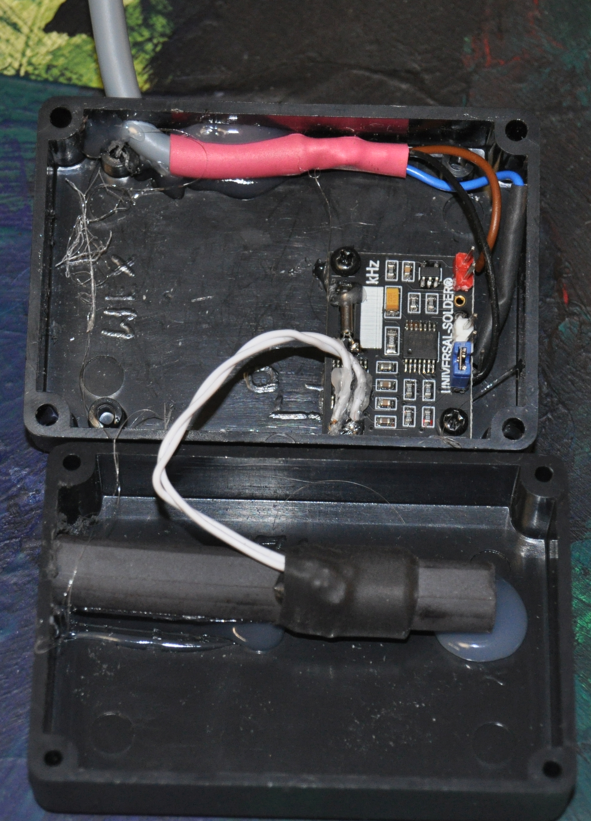
______
Note *): Might the Brexit reduce the power of the British admiralty so,
that the rest of the world can get rid of leap seconds.
Note **): The UTC people forgot to standardise a representation as seconds
count in the 50ies and the Posix people did it wrong in the 70ies.
DCF77 receiver
As said for technical and financial reasons we will use AM receiver modules. You get little boards + feritte antenna for below 10€ and better quality ones for ~14€. Adding the cost for a small plastic (!) case 5m cable – for the freedom to find a good place for the antenna – etc. you can have a DCF77 receiver directly connectable to a Raspberry Pi or another controller for less than 30€.
Properties:
o needs just one digital input port of the controller
- usually no OS support
- own DCF77 software / application needed (not rocket
science)
+ no battery needed
+ the module might be assembled together with *) and
+ be supplied from the controller (a Raspberry Pi e.g.)
+ the module might as well be put several meters away *) from
the controller.
+ the signal from one receiver can be distributed
to multiple **) controllers.
There are AM receiver modules below 10€ from Pollin and other vendors. The have been used with success. To test them before use an oscilloscope or a programme, like dcf77onPi. The log excerpt
test      µs stamp  pulse µs  sec res period µs    stamp  -  corr decode
DCF77 2.630.290.551   110060   7: F.M 2020225  15:43:06.133 -.188   |o|
DCF77 2.631.001.112   187210   0: T#b  710561  15:43:08.231 -. 13 minErr
DCF77 2.631.281.253    12020   1: s#b  280141  15:43:08.766 -.188   | |
DCF77 2.631.891.315   187991   2: T#b  610062  15:43:09.222 -. 40   |-|
DCF77 2.632.275.296    39190   3: F#b  383981  15:43:09.683 -.177   |o|
DCF77 2.632.771.357   176720   4: T#b  496061  15:43:10.205 -. 35   |-|
DCF77 2.632.815.177    34270   5: F#b   43820  15:43:10.558 -.  7   |o|
DCF77 2.632.860.417     6660   6: s#b   45240  15:43:10.575 -. 29   | |
DCF77 2.632.996.258    28510   7: s#b  135841  15:43:10.642 -. 18   | |
DCF77 2.633.033.588   130580   8: u#e 2120225  15:43:10.767 -. 17   | |
shows delivering erroneous (e) and undefined (u) results
as well as short / spiky (b s) modulation pulses and periods. This happens
with very bad receiving conditions (misdirected antenna or strong EMI) or
with low grade receiver modules.
Those cheap module’s circuit consists of an AM receiver chip (MAS6180 e.g.),
a filter quartz and almost nothing else. The out pin is very sensitive to EMI
seemingly acting as input. Some modules got broken (ending the joy on
the bargain) when connected a shielded cable (probe) was connected to an
output. Those “MAS6180 only” modules do always need an extra
OC output stage and supply
filters. Without you hardly get two minutes of fault free pulses.
______
Note *): It’s wiser to put the receiver module and its ferrite
antenna in an extra casing connected by a thin three wire (best shielded)
cable to the Pi or whatever controller.
Note **): Here a decoupling by multiple NPN open collector output stages
would be necessary and probably extra considerations on supply and
grounding etc. (But a stack of Pis with common supply and ground could
easily share one receiver.)
In the end it is better to spend 12..16€ for a module which comes with
all that, like e.g. the CANADUINO DCF77 receiver kit,
see image. It
comes with all necessary extras to the AM receiver chip: output stages,
power supply circuitry and even extra LEDs to optionally watch the
operation.
Nevertheless, as it allows an independent power supply for the receiver
(more than 3.3V and not from the PI) and the Pi, we always recommend an
extra OC output stage: NPN, hfe>200,
Rbase 100kΩ; Rcoll 10..100kΩ, Pi’s input pullup is OK.
The log Canaduino receiver excerpt was taken obviously on Mo, 2021-01-04, 15:08.
test      µs stamp  pulse µs  sec res period µs    stamp  -  corr decode
DCF77 0.522.295.426   183491 127: T.M 2001026  15:07:58.226 -. 83 mSrch
DCF77 0.523.295.068    82340   0: F.S  999642  15:08:00.126 -.182 minute
DCF77 0.524.293.681   182271   1: T.S  998613  15:08:01.225 -.185   |-|
DCF77 0.525.294.905   183870   2: T.S 1001224  15:08:02.226 -.183   |-|
:
DCF77 0.537.294.503   182981  14: T.S  998632  15:08:14.228 -. 84   |-|
DCF77 0.538.297.096    83881  15: F.S 1002593  15:08:15.126 -. 81 antOK
DCF77 0.539.296.099    80450  16: F.S  999003  15:08:16.126 -. 83 dlsKp
DCF77 0.540.295.321    83350  17: F.S  999222  15:08:17.127 -.181
DCF77 0.541.295.404   181171  18: T.S 1000083  15:08:18.224 -. 83 MEZ
DCF77 0.542.293.516    82270  19: F.S  998112  15:08:19.126 -.184 noLpS
DCF77 0.543.292.039   183611  20: T.S  998523  15:08:20.225 -.186 time:
:
DCF77 0.550.293.047    84330  27: F.S  999623  15:08:27.126 -. 87 hh:09
DCF77 0.551.294.209    85870  28: F.S 1001162  15:08:28.127 -.183 __:__
:
DCF77 0.557.292.804    84420  34: F.S  998672  15:08:34.127 -.185 15:mm
DCF77 0.558.291.607   184541  35: T.S  998803  15:08:35.226 -. 89 __:__
:
DCF77 0.564.292.682    84070  41: F.S  998203  15:08:41.126 -.187 04.mm.
DCF77 0.565.294.654   186470  42: T.S 1001972  15:08:42.228 -. 84
DCF77 0.566.293.897    83701  43: F.S  999243  15:08:43.127 -. 84
DCF77 0.567.289.019    84670  44: F.S  995122  15:08:44.126 -.189 Day:Mo
:
DCF77 0.572.290.832    88390  49: F.S 1000882  15:08:49.127 -.186 dd.01.
DCF77 0.573.291.855   185871  50: T.S 1001023  15:08:50.225 -. 86
:
DCF77 0.580.290.432    84920  57: F.S  997312  15:08:57.127 -.189 .2O21
DCF77 0.582.291.829   187961  58: T.M 2001397  15:08:58.227 -. 86 ______
DCF77 0.583.290.190    86009   0: F.S  998361  15:09:00.126 -. 90 minute
DCF77 0.584.292.262    89550   1: F.S 1002072  15:09:01.128 -.188   |o|
DCF77 0.585.293.105   188381   2: T.S 1000843  15:09:02.229 -.185   |-|
The excerpt shows no errors for the Canaduino module and good timing values. Logging over days gave 3 errors per hour. This can easily be ignored and bypassed. But 20 to more than 100 – as have been observed with cheap modules – threaten the availability of the time information. 100 per hour or more are a total failure.
Rightfully it has to said: It is possible to use the cheap “MAS6180 only”
modules with extra circuitry, meticulous antenna positioning and very “soft”
or forgiving timing criteria. One could even filter out one extra modulation
spike within a second by a mildly clever algorithm.
But is that worthwhile?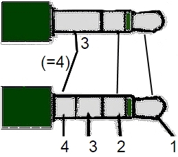 Just take a good module and enjoy the results.
Plugging the module to the µC
When having multiple receiving modules *) and/or some decoding devices
(like in our case Pis) I recommend a three pin
or even quadripolar 3.5mm jack connection – male and cable at the receiver,
female to the Pi. The (one) reasonable *) contact assignment is:
1 Ub +
2 DCF77 signal **)
3 / - AM receiver Off input ***)
4 / 3 Ground
There are complete AM receiver module with (of course *)) compatible 3.5mm
jacks commercially available under names like “Aktivantenne” or
“Filterantenne”. For still reasonable prices you are relieved from drilling
and soldering. On the other hand, in most cases of critical (jamming)
conditions they were outperformed by the homemade Canaduino based devices.
______
Note *): On plugging in and out this assignment won’t endanger signal pins.
Plugging with (same source) power on is practically safe.
With any other permutation it is not.
Note **): When available assign the receiver signal output to GPIO 15
(PIN10, UART in) as Pi input.
This might enable the use of raw DCF77 input drivers for NTP servers.
Their implementors chose to use a UART [sic!] instead of a simple binary
input for the pure binary AM signal.
Note ***a): This is usually the PDN (power down) pin of the MAS6180C AM
receiver IC. Hi or open means Off/ no operation.
Usually (and with the three pin connection) it would be tight
to ground.
This will be done automatically when the receivers quadripolar male
jack is put in three pin female plug on the µC side.
Note ***b): When using a Pi output to control receiver Off/On it is wise to
use an open collector output stage with a protective Rc of about 220 Ohm.
DCF77 implementation with a Pi
So far we shared the considerations for choosing DCF77 instead of battery powered “real time clocks” as an extra redundant time source for our embedded/distributed controller projects mostly with Raspberry Pis.
Algorithms and tricks for implementing the DCF77 decoding in C will be reported in the post Handling DCF77 AM signal with Raspberry Pi.
Comments
Want to leave a comment? Visit this post's issue page on GitHub.For commenting you will need a GitHub account.
This post shares the issue / comments with /dcf77decOnPi.html.
